
МЫ ЗАПУСТИЛИ НОВЫЙ САЙТ ПО АДРЕСУ: ZMARKETCHANGERS.COM
WE HAVE LAUNCHED NEW AND BETTER WEBSITE: ZMARKETCHANGERS.COM

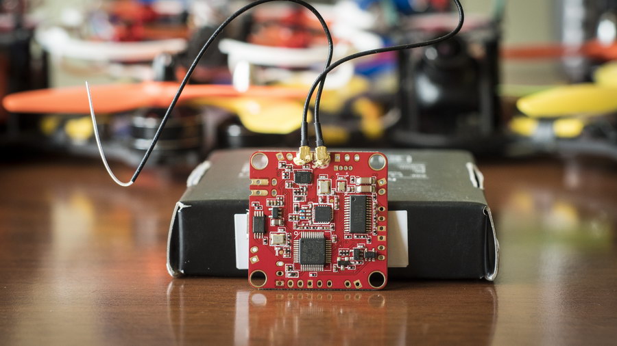
FrSKY continues to develop and give out new interesting products pleasing every single R|C hobby fan. This time, it is a new family of capable flight controllers for FPV racers based on recently introduced F4 boards + one additional F3-based board. To be honest, we always preferred FrSKY FCs over any others because they all have intergated FrSKY receivers (XSR is the most common) which saves final model flight weight, reduces the amount of cables and makes assembling process much easier. But not only that…

Today we would like to present 3 very new FrSKY FCs:
- FrSKY XSRF4O — F4-based FC with integrated FrSKY XSR, BF OSD and SDcard cslot for blackbox
- FrSKY XSRF4PO — F4-based FC with integrated FrSKY XSR, BF OSD, SDcard cslot for blackbox and PDB (with current and voltage sensors)
- FrSKY XSRF3PO — F3-based FC with integrated FrSKY XSR, BF OSD, SDcard cslot for blackbox and PDB (with current and voltage sensors)

First of all — as it is seen from the model names «XSR» stands for FrSKY XSR receiver (S.PORT full telemetry), «O» stands for BF OSD and «P» stands for PDB. Where else would you find so capable all-in-one boards with all those features intergrated on the factory? And having such FC as XSRF4PO or F3PO means that you would only end up with a single board in your model which would communicate with ESCs, VTX and camera. That’s it. Isn’t it an excellent idea? Having a single board inside the frame… No more huge amount of cables, no need to spend countless hours on soldering everything together… !
Buy XSRF3PO HERE
Buy XSRF4O HERE
Buy XSRF4PO HERE
Let’s start with more conservative XSRF4O:

Specifications:
- Based on F4 STM32F405 CPU
- Built-in 6-axis sensor MPU6000 (SPI) (Accelerometer/Gyro)
- Built-in BARO BMP280
- Integrated XSR receiver (SBUS, S.PORT), Full telemetry
- 1~16 channels SBUS output
- 1~6 channels PWM outputs
- Integrated BF OSD
- VTX and camera pads
- Buzzer control pads
- LED control pads
- Integrated voltage sensor
- Current sensor pad
- Dedicated V IN|GND pads
- Boot button
- Receiver BIND button
- Aditional S.PORT pads for XSR FW update and S.PORT sensors connection
- Built-in SDcard slot for BB
- Dimension: 36x36x6mm (LxWxH), with 30.5mm mounting holes
- Weight: 7,7g
- Operating voltage: 4-10V (5V is recommended)
This board is very common in terms of its shape and cababilities + has the intergated XSR recever . Requires power distribution board with 4-10V power supply to run. The layout looks like this:

Now, let’s jump to «PO» boards which are physically not so common: XSRF4PO

Specifications:
- Based on F4 STM32F405 CPU
- Built-in 6-axis sensor MPU6000 (SPI) (Accelerometer/Gyro)
- Built-in BARO BMP280
- Integrated XSR receiver (SBUS, S.PORT), Full telemetry
- 1~16 channels SBUS output
- 1~6 channels PWM outputs
- Integrated BF OSD
- VTX and camera pads
- Buzzer control pads
- LED control pads
- Integrated PDB (up to 6S)
- Integrated voltage sensor
- Integrated current sensor
- Boot button
- Receiver BIND button
- Aditional S.PORT pads for XSR FW update and S.PORT sensors connection
- Built-in SDcard slot for BB
- Weight: 14g
- Dimension: 60x36x6mm (LxWxH), with 30.5mm mounting holes

Exactly the same board to XSRF4O in terms of all capabilities but additionally intergrates power distribution board with dedicated ESC connections (SIG, BAT PWR, GND) and current sensor. Moreover, PDB is capable of 6S LiPO max input voltage. Layout looks like this:

This layout tells us that there is no 12V output. There is 5V output for camera or other devices, but you should use the appropriate VTX that would be able to accept raw flight battery voltage depending on the battery you’d use… Or you can add step-down voltage regulator.
And the last one is XSRF3PO:

Specifications:
- STM32F303 CPU – F3 Processor
- MPU6050 Gyro with I2C BUS
- Integrated Betaflight OSD
- Intergrated FrSKY XSR receiver (S.PORT. SBUS), Full telemetry
- Built in MicroSD card slot for BlackBox
- 1-8 PWM outputs (1-4 outputs are situated in the corners of the board)
- LED strip pads
- Buzzer pads
- OSD pads (camera + VTX)
- Integrated PDB (up to 6S)
- Integrated voltage sensor
- Integrated current sensor
- FC boot button
- XSR bind button
- Aditional S.PORT pads for XSR FW update and S.PORT sensors connection
- Weight: 14g
- Dimensions: 60x36x6mm (30.5mm mounting holes)

Very similar to XSRF4PO in terms of shape and PDB integration but really is a similar product to XSRF3O which we have reviewed last week. Its layout:

This layout tells us that there is no 12V output. There is 5V output for camera or other devices, but you should use the appropriate VTX that would be able to accept raw flight battery voltage depending on the battery you’d use… Or you can add step-down voltage regulator.
So, to summarize all FrSKY current FCs available:
- XSRF3E — F3Evo-based, when you want 8/8KHz gyro and PID loop rate + XSR receiver + telemetry
- XMPF3E — F3Evo-based, when you want 8/8KHz gyro and PID loop rate + XMP receiver + SDcard for blackbox and external OSD
- XSRF3O — F3-based, when you want 4/4KHz gyro and PID loop rate + XSR receiver + telemetry + BetaFlight OSD + SDcard for blackbox
- XSRF3PO — F3-based, when you want 4/4KHz gyro and PID loop rate + XSR receiver + telemetry + BetaFlight OSD + SDcard for blackbox + PDB + current sensor
- XSRF4O — F4-based, when you want up to 32/8KHz gyro and PID loop rate + XSR receiver + telemetry + BetaFlight OSD + SDcard for blackbox
- XSRF4PO — F4-based, when you want up to 32/8KHz gyro and PID loop rate + XSR receiver + telemetry + BetaFlight OSD + SDcard for blackbox + PDB + current sensor’

Seems that we have a good product line here that can satisfy almost any pilot with FrSKY radio…
There is one more FC from FrSKY which is called XMF3E. It is almost like XMPF3E but made to fit some smaller frames with board dimensions of 29x29mm. Main difference s are also: XM receiver with limited range of 300m and 4.2V power supply. This board would not be discussed further because it is not very suitable for the most popular 180-250 FPV copter frames.
Small note about F3 V/S F4-based flight controllers:
F4-based FCs mean that such FC would have faster processor (72 V/S 160MHz), more flash memory (256KB V/S 1MB), and sometimes more UART ports. What it means in real life is that F4 FC is capable of 32KHz looptime, while 8KHz is selected — leaves more room for processor to run all other features, capable of running recently introduced but resource-heavy «dynamic filter», can handle OSD by main processor instead of usind additional OSD unit. The only drawback compared to F3 is that F4 doesn’t have integrated inverter and using SBUS and S.PORT features might be tricky (all FrSKY FCs based on F4 do not have this issue.)
So, F4 boards would only be required if you have ESCs that are capable of running much faster types of communication than OneShot 125 or 42. Only if you have DShot600 and more capable ECSs — it is reasonable to jump to F4 instead of F3 or F3Evo. Or, if you require more than 3 UARTs or want so many features enabled at a time that your F3Evo|F3 processor shows more than 30% load figures on a bench.
In the box:


All of the controllers come in a small boxes with English user manual and a set of soldering pins for all available pads. But in case of FCs with integrated PDB (XSRF4PO and XSRF3PO) we would also find XT60 connector and soft mounting spacers made of rubber. The package is nothing to worry about during the transportation. English user manual is ok and it really helps to understand board layouts and initial BetaFlight setup.
Formfactor:

As we’ve already said — XSRF4O is a regular box-shaped board with 30,5×30,5mm mounting holes (36×36 board size) that would fit any kind of FPV quad racing frame but requires any PDB with 4-10V power supply. ESC PWM singnals are located at the corners of the board for easy reach. USB connection is directed to the side of the board and ESCs numbers are located so that it would correspond to BF setup in case if the board located properly without applying yaw compensation.
In contrary, XSRF4PO and F3PO are unique and despite having the same mounting hole dimensions (30,5×30,5mm) — they both have rectangular shape with 60mm in length (width is regular 36mm). LiPO battery connections are at the back and ESC connections are at corners, corresponding to BF ESC setup. USB port is on the side.

This means that NOT every frame is capable of accepting such FCs. For example, I have KDS Kylin 210 square-shaped frame which would not let FrSKY «PO» fit directly. My FPV camera mount and VTX back vertical mount stand closer to each other than 60mm needed for this FCs and frame aluminum standoffs also prevent using these. If I had some longer frame (1-2cm) I wouldn’t have an issue.

So, either to change the frame or try to fit «PO» FCs transversely. In this case, either board would protrude from both sides of a frame to about 1cm…

Not very aesthetical and safe. Moreover, turning FC around 90 degrees would mean that ESC connections at the corners of the board won’t correspond to ESCs on the arms, forcing me to remap the resources in CLI section of BetaFlight setup. Everything is possible and acceptable but the best solution would still be changing the frame to something more suitable.
On the other hand, thinking of the advantages of such all-in-one board setup — I would finally go with the new more suitable frames… I am just amazed with how easy and neat such setup should be to assemble, with much less of cable connections and soldering required. The weight should also be slightly reduced due to no wires between PDB and FC + due to PDB FC integration.
Initial Betaflight Configuration and FW:

In contrary to previous FrSKY controllers XSRF3E and XMPF3E which should be identified as SpRacing F3Evo during FW upgrade using BetaFlight GUI, all newer boards would have the following names:
- XSRF3O & XSRF3PO — FRSKY F3 in BetaFlight FW upgrade list
- XSRF4O & XSRF4PO — FRSKY F4 in BetaFlight FW upgrade list
All these boards have the current FW version 3.2.0 RC2 with all features working properly and supporting the newest BF tabs and settings. All boards feature dedicated BOOT button for easy DFU mode access when FW flash in necessary.
FrSKY boards require some defaults in order for the intergrated XSR work correctly and that are initially set on the factory, supplied in the FW files and mentioned in manuals. Those are:
XSRF3O & XSRF3PO
- UART2 should be Serial RX
- UART3 should be SmartPort
- Receiver Mode should be RX_Serial
- Serial Receiver Provider should be SBUS
- RSSI_ADC Analog RSSI input should be disabled
- RSSI CH should be CH8
XSRF4O & XSRF4PO
- UART1 should be Serial RX
- UART6 should be SmartPort
- Receiver Mode should be RX_Serial
- Serial Receiver Provider should be SBUS
- RSSI_ADC Analog RSSI input should be disabled
- RSSI CH should be CH8
All boards would incorporate BF OSD setup, Battery Voltage&Current, LED strip and BlackBox with SDcard tabs in addition to all other BetaFlight setup tabs and features. All those tabs should be setup as it is usually done on all other boards or additional boards with the same features. Nothing strange or unexpected in settings.
Note: intergrated XSR receiver in all FCs has physical S.PORT pads. Those pads can be used to flash XSR with the newest FW versions, change FW region (from FCC to EU LBT and vise-versa) and even to connect other S.PORT telemetry sensors in chain. But remember that you cannot flash integrated XSR with the FW from the stand-alone XSR receiver. You should locate dedicated FW for integrated XSR on FrSKY website.
Tests, flights and recommendations:

We have already tested XSRF3O board some time ago (in our previous review). It flies good, easy to tune, all features work as expected. It replaced our previous SpRacing F3 board because XSRF3O intergates receiver, OSD and SDCard slot making our FPV copter easier to assemble, more advanced in terms of amount of features and less heavy (only 288g for 210-class frame). Integrated XSR seems to be working exactly the same as any other stand-alone XSR receiver. The range is the same…
Consequently, the newer XSRF3PO would act very similar if not identical… This board shares the same features and specifications… The only difference is that «PO» would also act as PDB making the whole setup even more convenient. We have checked all the features on the bench — everything working fine, but we cannot really make any flight checks now because we are in a process of making / ordering some suitable frames that would accept such rectangular design. But we have already tested the amount of noise or interference from PDB to camera + VTX on the bench with motors and ESCs running — PDB quality seems to be very good as there is no visible picture problems or interference lines. It might happen so that we wouldn’t even need the additional capacitors to filter out the noise.
Other 2 boards that are based on F4 are also yet to be tested thoroughly. I have already tuned and flown XSRF4O which was set to 8/8KHz looptime for my HobbyWing XRotor DShot600 ESCs and XRotor 2205/2300kv motors. I haven’t noticed much of a difference with XSRF3Evo board which had 8/4KHz looptime configuration on the same setup. A bit more precise and a bit more predictable. But I would continue to tune PID and other settings to polish the flight capabilities of the board trying to find the obvious advanyages of F4 boards over F3Evo.
As to XSF4PO would also wait for the newer frames to arrive. All bench tests and settings show consistent and expected behavior. All features work as described. But we would still conduct some flight tests on order to share it with our readers. As already mentioned for F3PO — PDB quality is good and picture quality from FPV camera and VTX shows no signs of distructive noise.
We would add flight test videos to this review soon.
Note: all FrSKY flight controllers with XSR receivers have detachable XSR antennas. So, antenna swap is not a problem.
Conclusion:
I have 4 FPV racing quads that I use regularly. All of them are based on FrSKY XSRF3E (F3Evo), XSRF3O and SpRacing F3 FCs. I would definitely get rid of SpRacing F3 boards just because they don’t have the necessary features and require additional stuff, wiring and soldering… I would definitely change it to FrSKY FCs with integrated XSR receivers and other features. Those of my quads that have ESCs capable of DShot600 (and more) are already using XSRF4O and would be using XSRF4PO in future because F4-based boards are able to handle >8KHz looptime and don’t have any stability or processor calculation power shortage issues. But those quads that have OneShot ESCs would be left on XSRF3O and XSRF3PO flight controllers because 4/4KHz is totally enough in this case.
Anyway, concerning that I have already tried what it is like to build and use a racing quad with all-in-one boars — it seems that I would never go back to all-separate solutions. All-in-one boards make the whole setup much more convenient to assemble, much easier to look after it and more neat. In addition to that, all described above boards originate from a good manufacturer — FrSKY — and incorporate one the most popular receiver in FPV racing world — XSR. This is everything that I need for all of my quads!!!
Buy XSRF3PO HERE
Buy XSRF4O HERE
Buy XSRF4PO HERE


